Paper(1)Perception and Motion Planning for Pick-and-Place of Dynamic Object
Cowley, A., Cohen, B., Marshall, W., Taylor, C. J., & Likhachev, M. (2013, November). Perception and motion planning for pick-and-place of dynamic objects. In 2013 IEEE/RSJ International Conference on Intelligent Robots and Systems (pp. 816-823). IEEE.
PR2 被广泛应用于tabletop manipulation research。本文的系统设计是基于装有RGB-D sensor和自身姿态sensor的PR2。
The perception system
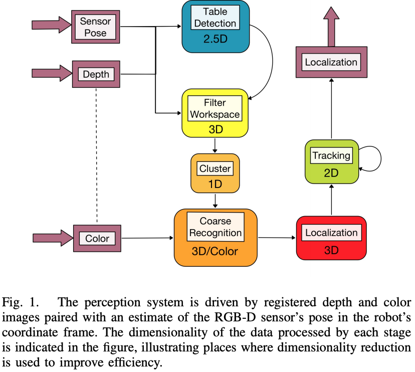
The overall procedure is that table geometry is extracted to perform an initial interpretation of the scene that disregards a large fraction of sensor data. Detected points that lie above the work surface are clustered, and those clusters are recognized and localized to provide pose estimation of identifiable objects. The convention followed is that common to ROS: a right-handed coordinate system with the X-axis extending forward from the robot, the Y-axis extending to the robot’s left, and the Z-axis extending up from the base.
Step 1 for Perception: Table Surface Extraction
During execution, the table height, orientation, and extents are periodically(every 10 seconds) re-estimated from direct observation.
Step 2 for Perception: Coarse Object Recognition and Localization
Upon the arrival of a pair of registered depth and color images, all points not within a space above the table geometry previously extracted are immediately removed.
The remaining points are projected onto the line corresponding to the table orientation and then clustered using histogram analysis. Then coarse classifiers in these clusters use color statistics and size limits to reject the obvious object type mismatches. All clusters
recognized by at least one coarse recognizer have their centroids computed, and are fed forward in the system.
Step 3 for Perception: Refined Recognition and Localization
Observed point clusters are recognized by finding a 2D transformation that minimizes a cost function whose minimal manifold corresponds to the surface of the object model when summed over all observed points.
The image coordinates of the relevant points are translated to a cropped coordinate frame containing only the observed points.
These coordinates are then paired with the 3D points reconstructed from the depth data, transformed into the object’s coordinate frame using the points’ centroid(从第二步得到的centroid) as the origin, and loaded onto the GPU.
When the optimization process has finished, the average distance from each point in the observation under the minimal-cost transformation to the object model is considered to determine if we have a successful identification.
Step 4 for Perception: Tracking
The above process is applied to a small number of observed point clusters, while the rest are left as unidentified.
All clusters are then passed to a tracking component that models the kinematics of both identified and unidentified point clouds.
Observation integration is achieved by maintaining a track state that includes both object position and velocity in a Kalman filtering framework. When a recognized object track is reported, an estimate of its position on the table plane is extracted from the
Kalman filter, and a bounded history of orientation estimates provided by the localization optimization.
The manipulation
The manipulation pipeline is comprised of three main components:
- Grasping
- Motion planning
- Execution
Step 1 for manipulation: Grasping
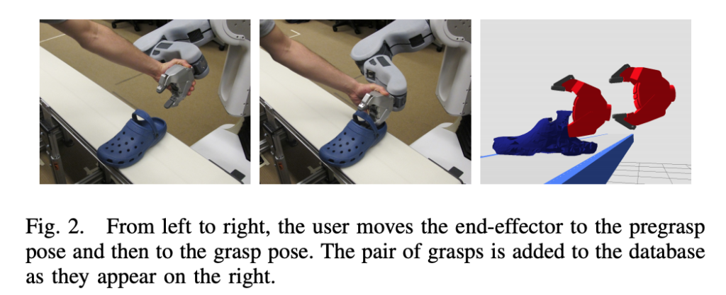
To simplify grasp planning, we exploit the fact that we have a well-defined set of objects to be manipulated. This allows us to restrict the set of grasps for each type of object to ones that we have previously tested and saved in a database.
The process of picking up an object requires the end-effector to move between three different poses:
- Pre-grasp: An end-effector pose that is offset from the object. The motion planner is used to plan a collision-free trajectory from the arm’s waiting configuration to a valid configuration with the end-effector at the pre-grasp pose.
- Grasp – The pose of the end-effector in which its fingers are in a position to reliably enclose part of the object. A collision trajectory is needed to bring the end effector from the pre-grasp pose into a grasp pose that can contact the target object.
- Post-grasp: The end-effector pose after it moved away from the table surface with the object grasped. The motion planner is then used to compute a feasible motion for the arm that takes the end-effector from the post-grasp to the desired location to place the object.
通常我们对不同的object会有不同的 (Pre-grasp, Grasp) pair,The set of (Pre-grasp, Grasp) pair for each object contains 2到20种。但是对于postgrasp,we found that a single set of post-grasp positions can be used for all object types so the user is not required to record a post-grasp for each object.
Select the right grasp for each object: Upon detection of a new object, we use its estimated pose and velocity to predict when the object will arrive at the center of the workspace and the 6-DOF pose of the object. The object type is used to retrieve a set of pre-grasps and grasps from the database. 根据the predicted pose of the object,我们从dataset中选择对应的(Pre-grasp, Grasp) pair,然后对应的算出end-effector在pre-grasp和grasp时对应的pose。
接着,我们需要对该(Pre-grasp, Grasp) pair进行feasibility check。首先是确认pre-grasp和grasp没有正好跟object的速度在一个方向,其次就是依据(Pre-grasp, Grasp) pair的end-effector的pose,利用inverse dynamics对应的计算出joint configuration,看看是不是kinematic feasibility。
Therefore, instead of choosing a single (pre-grasp,grasp) tuple to target, the entire set of pre-grasps based on the predicted pose of the object is sent to the motion planner. When the planner finds a collision-free trajectory for one single pre-grasp, 我们就加the corresponding grasp pose. 有了grasp pose,我们可以很容易得到post-grasp pose that is as far from the table as possible, 然后check对应的kinematic feasibility(inverse kinematics)。
The next step is to determine whether there is enough time for the robot to execute both trajectories (waiting configuration to pre-grasp pose, and pre-grasp pose to grasp and to post-grasp pose) in time to pick up the object when the object will arrive at the center of the workspace.
After the end-effector opens, allowing the object to drop into the desired bin, the arm
returns to the waiting configuration.